
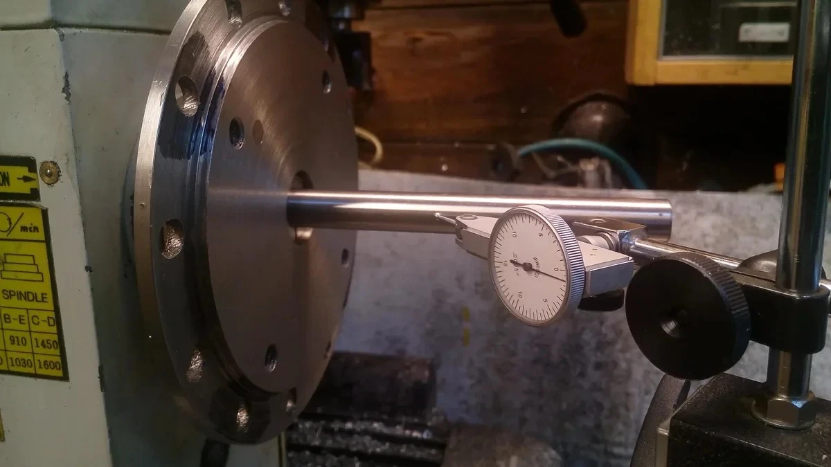
Achieving sub-micron dimensional tolerances and mirror-like surface finishes (Ra < 0.4 µm) on CNC turning centers requires overcoming two fundamental physical adversaries: mechanical chatter vibration and thermal growth.
Even a minor thermal gradient of 3°C across a lathe headstock can displace the spindle centerline by 0.015 mm (15 microns), causing out-of-roundness, tapered cylindrical bores, and scrapped parts in tight-tolerance production.
This engineering whitepaper outlines the root causes of vibration and thermal drift in CNC lathes and presents proven countermeasures to maintain relentless machining accuracy.
1. The Physics of Turning Vibration: Forced vs. Self-Excited Chatter
Machining vibration falls into two distinct categories:
VIBRATION PHENOMENON          PRIMARY CAUSE                          SHOP FLOOR SYMPTOM
--------------------------------------------------------------------------------------------------
1. Forced Vibration       Unbalanced chuck, damaged spindle       Rhythmic, periodic surface ripples
                          bearings, uneven workpiece forging     at exact spindle rotation frequency

2. Self-Excited Chatter   Regenerative cutting wave interaction   High-pitched screeching sound,
                          between tool edge and wavy chip surface  random diamond or scalloped pattern
Eliminating Self-Excited Regenerative Chatter
Regenerative chatter occurs when the vibration from a previous turning revolution creates an undulating surface that excites the cutting tool on the subsequent pass.
- Rule of Tool Overhang: Keep tool overhang ratio ($L/D$) below $3:1$ for solid steel toolholders and below $5:1$ for heavy-metal densalloy or carbide-shank boring bars. For deeper bore depths exceeding $7:1$, deploy internally tuned mass-damped boring bars.
- Insert Geometry Optimization: Use an insert with a smaller nose radius ($0.4\text{ mm}$ instead of $0.8\text{ mm}$ or $1.2\text{ mm}$) to reduce radial thrust forces ($F_r$) that push the toolholder sideways into resonance.
- Variable Spindle Speed Control (SSV): Modern CNC controllers (FANUC, Siemens, SYNTEC) support Spindle Speed Variation. By continuously modulating spindle RPM by $\pm 50\text{ to }100\text{ RPM}$ during the cut, the phase relationship between surface waves is disrupted, preventing resonant chatter from locking in.
2. Managing Thermal Displacement & Spindle Growth
In continuous production turning, frictional heat from high-speed spindle bearings, hydraulic oil pumps, and hot chip accumulation creates significant thermal expansion along the Z-axis (spindle elongation) and X-axis (centerline elevation).
          +-------------------------------------------------------------+
          |             HEADSTOCK THERMAL GROWTH PROFILE                |
          |                                                             |
          |                 ▲ X-Axis Elevation (+10 to +25 µm)          |
          |                 |                                           |
          |      [ MOTOR ]--[ HEADSTOCK ]=======[ CHUCK ] ► Z-Axis      |
          |                                       Elongation            |
          |                                       (+15 to +35 µm)       |
          +-------------------------------------------------------------+
Countermeasures for Thermal Equilibrium
- Refrigerated Spindle Oil Chillers: High-speed turning centers (such as Qingluan TCK50/TCK52) circulate temperature-controlled oil around the spindle cartridge jacket, tracking ambient shop floor temperature within $\pm 0.5^\circ\text{C}$ to neutralize thermal rise before it transfers to the casting.
- Thermal-Symmetrical Bed Casting: Monolithic 30°/45° slant bed architecture features symmetrical triangular cross-sections that expand uniformly upward and outward, preserving the relative horizontal alignment between the tool turret and the spindle center.
- Dedicated Warm-up Cycles: Never begin finish-turning tight-tolerance diameters on a cold machine. Run a 15-minute automated warm-up program cycling the spindle at 30%, 60%, and 80% maximum RPM to reach thermal steady state.
3. Toolholding Rigidity: Block Turrets vs. Wedge Toolposts
The connection interface between the toolholder and the carriage is the mechanical fuse of the machine:
- BMT55 / BMT65 Base Mount Tooling: The toolholder bolts directly against the ground perimeter of the turret disc with four hardened cap screws and dual precision locator keys. This achieves over 300% higher torsional stiffness compared to traditional VDI shank clamping, allowing aggressive high-feed parting and deep grooving without tool deflection.
- Pre-tensioned C3 Ball Screws: Double-nut pre-tensioned ball screws anchored by quadruple angular-contact thrust bearings prevent axial screw elongation caused by continuous high-speed rapid traverse friction.
4. Workpiece Clamping & Hydraulic Chuck Balancing
- True Dynamic Chuck Balancing: When running 8-inch or 10-inch 3-jaw hydraulic chucks above 3,000 RPM, centrifugal force reduces effective jaw clamping pressure by up to 50%. Always calibrate hydraulic chuck cylinder pressure using an electronic wireless gripping force meter, and ensure chuck bodies are dynamically balanced to ISO 1940 G2.5 standards.
- Pneumatic or Hydraulic Tailstock Thrust: Long shafts must be supported with precision live centers featuring runout under $0.003\text{ mm}$. Set tailstock hydraulic thrust pressure according to shaft diameter to prevent axial bowing.
Consult Qingluan Application Engineers
Encountering stubborn chatter marks or thermal dimensional drift on your production line? Send your part drawing, material specifications, and current cycle parameters to [email protected]. Our factory application engineers are available to optimize your tooling geometry, feeds, speeds, and machine setup.